Download Dell SONiC Deploy.D-SNC-DY-00.VCEplus.2024-08-23.30q.vcex
| Vendor: | Dell |
| Exam Code: | D-SNC-DY-00 |
| Exam Name: | Dell SONiC Deploy |
| Date: | Aug 23, 2024 |
| File Size: | 688 KB |
| Downloads: | 2 |
How to open VCEX files?
Files with VCEX extension can be opened by ProfExam Simulator.
Discount: 20%
Demo Questions
Question 1
Refer to the exhibit.

What type of route is shown?
- Type 3 host route from external VTEP
- Type 2 host route from another VTEP
- Type 3 host route from another VTEP
- Type 5 host route from another VTEP
Correct answer: B
Explanation:
The exhibit shows a BGP EVPN route in a VXLAN environment. The route type can be determined based on the details provided. Type 2 routes in BGP EVPN are used to advertise MAC address reachability information between VTEPs (Virtual Tunnel End Points). The exhibit indicates a host route from another VTEP, which corresponds to a Type 2 route.Dell Technologies SONiC documentationBGP EVPN Configuration Guide The exhibit shows a BGP EVPN route in a VXLAN environment. The route type can be determined based on the details provided. Type 2 routes in BGP EVPN are used to advertise MAC address reachability information between VTEPs (Virtual Tunnel End Points). The exhibit indicates a host route from another VTEP, which corresponds to a Type 2 route.
Dell Technologies SONiC documentation
BGP EVPN Configuration Guide
Question 2
What is ECMP?
- A Layer 3 routing feature to forward traffic using multiple available paths
- A routing protocol database filter supporting a maximum of four paths
- A round-robin path distribution mechanism
- A routing protocol with multipath support
Correct answer: A
Explanation:
ECMP (Equal-Cost Multi-Path) is a Layer 3 routing feature that allows traffic to be forwarded using multiple available paths of equal cost. This improves bandwidth utilization and provides redundancy. ECMP is commonly used in modern networks to optimize the flow of traffic and increase the resiliency of network connections.Dell Technologies SONiC documentationECMP Configuration Guide ECMP (Equal-Cost Multi-Path) is a Layer 3 routing feature that allows traffic to be forwarded using multiple available paths of equal cost. This improves bandwidth utilization and provides redundancy. ECMP is commonly used in modern networks to optimize the flow of traffic and increase the resiliency of network connections.
Dell Technologies SONiC documentation
ECMP Configuration Guide
Question 3
What is a correct use-case scenario for ZTP in Enterprise SONiC?
- The user wants single pane of glass monitoring.
- The user wants to replace a failed unit and use an automatic script.
- The user wants multivendor switch deployment.
- The user wants to configure the switch manually using the CLI.
Correct answer: B
Explanation:
ZTP (Zero Touch Provisioning) is used to automate the configuration of switches, especially useful in scenarios where a failed unit needs to be replaced. By using ZTP, the switch can automatically download and apply the necessary configuration scripts upon boot-up, reducing the need for manual intervention and speeding up the deployment process.Dell Technologies SONiC documentationZero Touch Provisioning Guide ZTP (Zero Touch Provisioning) is used to automate the configuration of switches, especially useful in scenarios where a failed unit needs to be replaced. By using ZTP, the switch can automatically download and apply the necessary configuration scripts upon boot-up, reducing the need for manual intervention and speeding up the deployment process.
Dell Technologies SONiC documentation
Zero Touch Provisioning Guide
Question 4
What is the purpose of the write erase boot command option?
- Delete the startup and enable zero touch provisioning.
- Remove user-installed packages and tile changes.
- Delete the startup configuration and the management interface configuration.
- Delete the running configuration and all user accounts.
Correct answer: A
Explanation:
The write erase boot command option deletes the startup configuration and enables zero touch provisioning (ZTP). This is used to reset the switch to its default state and prepare it for automated configuration through ZTP.Dell Technologies SONiC Command Reference GuideSwitch Configuration Guide The write erase boot command option deletes the startup configuration and enables zero touch provisioning (ZTP). This is used to reset the switch to its default state and prepare it for automated configuration through ZTP.
Dell Technologies SONiC Command Reference Guide
Switch Configuration Guide
Question 5
VLAN 40 is configured in Switch A with an anycast-address of 192.168.40.254/24. The ARP neighbor suppression is enabled. Use the simulator to create a VTEP named vtep1 and assign an IP address of 10.10.10.1. Map the VNI 400 to VLAN 40.

- see the explanation for all step by step solution with all explanation
Correct answer: A
Explanation:
Here are the steps to create the VTEP and map the VNI to the VLAN:Enter Configuration Mode:SwitchA# configure terminalCreate VTEP Interface:SwitchA(config)# interface vtep1SwitchA(config-if-vtep1)# ip address 10.10.10.1/24SwitchA(config-if-vtep1)# exitMap VNI 400 to VLAN 40:SwitchA(config)# vlan 40SwitchA(config-vlan)# vn-segment 400SwitchA(config-vlan)# exitEnable ARP Neighbor Suppression:SwitchA(config)# interface Vlan40SwitchA(config-if-Vlan40)# ip address 192.168.40.254/24SwitchA(config-if-Vlan40)# vxlan arp-suppressionSwitchA(config-if-Vlan40)# exitSave Configuration:SwitchA# write memoryEnter Configuration Mode:Begin by entering the global configuration mode to make changes to the switch configuration.Create VTEP Interface:Enter the interface configuration mode for the VTEP interface named vtep1 using interface vtep1.Assign the IP address 10.10.10.1/24 to the VTEP interface using the ip address command.Exit the interface configuration mode.Map VNI 400 to VLAN 40:Enter the VLAN configuration mode for VLAN 40 using vlan 40.Map the VNI 400 to VLAN 40 using the vn-segment 400 command.Exit the VLAN configuration mode.Enable ARP Neighbor Suppression:Enter the interface configuration mode for VLAN 40 using interface Vlan40.Assign the anycast IP address 192.168.40.254/24 to the VLAN interface using the ip address command.Enable ARP neighbor suppression using the vxlan arp-suppression command.Exit the interface configuration mode.Save Configuration:Save the configuration to ensure the changes persist after a reboot using the write memory command.Dell Technologies Networking - SONiCDell Enterprise SONiC Deployment GuideThese steps provide a comprehensive guide to configure a VTEP and map the VNI to VLAN 40 on Switch A, ensuring the specific requirements for IP addressing and ARP neighbor suppression are met. Here are the steps to create the VTEP and map the VNI to the VLAN:
Enter Configuration Mode:
SwitchA# configure terminal
Create VTEP Interface:
SwitchA(config)# interface vtep1
SwitchA(config-if-vtep1)# ip address 10.10.10.1/24
SwitchA(config-if-vtep1)# exit
Map VNI 400 to VLAN 40:
SwitchA(config)# vlan 40
SwitchA(config-vlan)# vn-segment 400
SwitchA(config-vlan)# exit
Enable ARP Neighbor Suppression:
SwitchA(config)# interface Vlan40
SwitchA(config-if-Vlan40)# ip address 192.168.40.254/24
SwitchA(config-if-Vlan40)# vxlan arp-suppression
SwitchA(config-if-Vlan40)# exit
Save Configuration:
SwitchA# write memory
Enter Configuration Mode:
Begin by entering the global configuration mode to make changes to the switch configuration.
Create VTEP Interface:
Enter the interface configuration mode for the VTEP interface named vtep1 using interface vtep1.
Assign the IP address 10.10.10.1/24 to the VTEP interface using the ip address command.
Exit the interface configuration mode.
Map VNI 400 to VLAN 40:
Enter the VLAN configuration mode for VLAN 40 using vlan 40.
Map the VNI 400 to VLAN 40 using the vn-segment 400 command.
Exit the VLAN configuration mode.
Enable ARP Neighbor Suppression:
Enter the interface configuration mode for VLAN 40 using interface Vlan40.
Assign the anycast IP address 192.168.40.254/24 to the VLAN interface using the ip address command.
Enable ARP neighbor suppression using the vxlan arp-suppression command.
Exit the interface configuration mode.
Save Configuration:
Save the configuration to ensure the changes persist after a reboot using the write memory command.
Dell Technologies Networking - SONiC
Dell Enterprise SONiC Deployment Guide
These steps provide a comprehensive guide to configure a VTEP and map the VNI to VLAN 40 on Switch A, ensuring the specific requirements for IP addressing and ARP neighbor suppression are met.
Question 6
A customer must configure a peer link between two switches in the L2 MC-LAG scenario.
SwitchB has already been configured. Configure the peer link on SwitchA.
Use the following configuration information:
MC-LAG domain 1
VLAN 101
Peer link Port-Channel 100
SwitchA IP: 192.168.1.1/24
SwitchB IP: 192.168.1.2/24
MC-LAG system MAC: 00:00:00:11:11:11
The physical ports to connect the peer switch are Eth 1/5 and Eth 1/6 for each switch.


- see the explanation for all step by step solution with all explanation
Correct answer: A
Explanation:
Here are the steps to configure the peer link on SwitchA:Enter Configuration Mode:SwitchA# configure terminalCreate VLAN 101:SwitchA(config)# vlan 101Create Port-Channel 100:SwitchA(config)# interface port-channel 100SwitchA(config-if-po100)# switchport mode trunkSwitchA(config-if-po100)# switchport trunk allowed vlan 101SwitchA(config-if-po100)# exitAssign Physical Interfaces to Port-Channel 100:SwitchA(config)# interface ethernet 1/5SwitchA(config-if-eth1/5)# channel-group 100 mode activeSwitchA(config-if-eth1/5)# exitSwitchA(config)# interface ethernet 1/6SwitchA(config-if-eth1/6)# channel-group 100 mode activeSwitchA(config-if-eth1/6)# exitConfigure MC-LAG Domain 1:SwitchA(config)# mclag domain 1SwitchA(config-mclag-domain)# peer-link port-channel 100SwitchA(config-mclag-domain)# local-ip 192.168.1.1SwitchA(config-mclag-domain)# peer-ip 192.168.1.2SwitchA(config-mclag-domain)# system-mac 00:00:00:11:11:11SwitchA(config-mclag-domain)# exitSave Configuration:SwitchA# write memoryComprehensive Detailed Step by Step Explanation withReference:Enter Configuration Mode:Begin by entering the global configuration mode to make changes to the switch configuration.Create VLAN 101:Create VLAN 101 to be used for the MC-LAG peer link communication.Create Port-Channel 100:Enter the port channel interface configuration mode using interface port-channel 100.Set the port channel to trunk mode with switchport mode trunk.Allow VLAN 101 on the trunk with switchport trunk allowed vlan 101.Exit the port channel interface configuration mode.Assign Physical Interfaces to Port-Channel 100:Enter interface configuration mode for ethernet 1/5 and assign it to port channel 100 using the channel-group 100 mode active command.Exit the interface configuration mode.Repeat the same steps for ethernet 1/6.Configure MC-LAG Domain 1:Enter the MC-LAG domain configuration mode using mclag domain 1.Specify the peer link port channel with peer-link port-channel 100.Configure the local IP address as 192.168.1.1 using local-ip 192.168.1.1.Configure the peer IP address as 192.168.1.2 using peer-ip 192.168.1.2.Set the MC-LAG system MAC address using system-mac 00:00:00:11:11:11.Exit the MC-LAG domain configuration mode.Save Configuration:Save the configuration to ensure the changes persist after a reboot using the write memory command.Dell Technologies Networking - SONiCDell Enterprise SONiC Deployment GuideThese steps provide a comprehensive guide to configure the peer link for an MC-LAG scenario on SwitchA, ensuring the specific requirements for IP addressing, VLAN configuration, and port channel setup are met. Here are the steps to configure the peer link on SwitchA:
Enter Configuration Mode:
SwitchA# configure terminal
Create VLAN 101:
SwitchA(config)# vlan 101
Create Port-Channel 100:
SwitchA(config)# interface port-channel 100
SwitchA(config-if-po100)# switchport mode trunk
SwitchA(config-if-po100)# switchport trunk allowed vlan 101
SwitchA(config-if-po100)# exit
Assign Physical Interfaces to Port-Channel 100:
SwitchA(config)# interface ethernet 1/5
SwitchA(config-if-eth1/5)# channel-group 100 mode active
SwitchA(config-if-eth1/5)# exit
SwitchA(config)# interface ethernet 1/6
SwitchA(config-if-eth1/6)# channel-group 100 mode active
SwitchA(config-if-eth1/6)# exit
Configure MC-LAG Domain 1:
SwitchA(config)# mclag domain 1
SwitchA(config-mclag-domain)# peer-link port-channel 100
SwitchA(config-mclag-domain)# local-ip 192.168.1.1
SwitchA(config-mclag-domain)# peer-ip 192.168.1.2
SwitchA(config-mclag-domain)# system-mac 00:00:00:11:11:11
SwitchA(config-mclag-domain)# exit
Save Configuration:
SwitchA# write memory
Comprehensive Detailed Step by Step Explanation with
Reference:
Enter Configuration Mode:
Begin by entering the global configuration mode to make changes to the switch configuration.
Create VLAN 101:
Create VLAN 101 to be used for the MC-LAG peer link communication.
Create Port-Channel 100:
Enter the port channel interface configuration mode using interface port-channel 100.
Set the port channel to trunk mode with switchport mode trunk.
Allow VLAN 101 on the trunk with switchport trunk allowed vlan 101.
Exit the port channel interface configuration mode.
Assign Physical Interfaces to Port-Channel 100:
Enter interface configuration mode for ethernet 1/5 and assign it to port channel 100 using the channel-group 100 mode active command.
Exit the interface configuration mode.
Repeat the same steps for ethernet 1/6.
Configure MC-LAG Domain 1:
Enter the MC-LAG domain configuration mode using mclag domain 1.
Specify the peer link port channel with peer-link port-channel 100.
Configure the local IP address as 192.168.1.1 using local-ip 192.168.1.1.
Configure the peer IP address as 192.168.1.2 using peer-ip 192.168.1.2.
Set the MC-LAG system MAC address using system-mac 00:00:00:11:11:11.
Exit the MC-LAG domain configuration mode.
Save Configuration:
Save the configuration to ensure the changes persist after a reboot using the write memory command.
Dell Technologies Networking - SONiC
Dell Enterprise SONiC Deployment Guide
These steps provide a comprehensive guide to configure the peer link for an MC-LAG scenario on SwitchA, ensuring the specific requirements for IP addressing, VLAN configuration, and port channel setup are met.
Question 7
Configure a VRF called 'VrfGreen' and the static route in it to network 172.16.128.64/28 through next-hop 10.10.10.1. Set an administrative distance of 213.

- see the explanation for all step by step solution with all explanation
Correct answer: A
Explanation:
Here are the steps to configure the VRF and the static route:Enter Configuration Mode:sonic# configure terminalCreate VRF 'VrfGreen':sonic(config)# ip vrf VrfGreenConfigure the Static Route:sonic(config)# ip route vrf VrfGreen 172.16.128.64/28 10.10.10.1 213Save Configuration:sonic# write memoryComprehensive Detailed Step by Step Explanation withReference:Enter Configuration Mode:Begin by entering the global configuration mode to make changes to the switch configuration.Create VRF 'VrfGreen':Use the command ip vrf VrfGreen to create a new VRF named 'VrfGreen'. This command sets up a new VRF instance which will isolate the routing table for this VRF from the global routing table and other VRFs.Configure the Static Route:Use the command ip route vrf VrfGreen 172.16.128.64/28 10.10.10.1 213 to configure the static route.ip route vrf VrfGreen specifies that the route should be added to the 'VrfGreen' VRF.172.16.128.64/28 is the destination network.10.10.10.1 is the next-hop IP address.213 is the administrative distance, which in this case is set to a non-default value to influence route preference.Save Configuration:Save the configuration to ensure the changes persist after a reboot using the write memory command.Dell Technologies Networking - SONiCDell Enterprise SONiC Deployment GuideThese steps provide a comprehensive guide to configure a VRF and a static route within that VRF on a SONiC-based switch, ensuring the specific requirements for routing and administrative distance are met. Here are the steps to configure the VRF and the static route:
Enter Configuration Mode:
sonic# configure terminal
Create VRF 'VrfGreen':
sonic(config)# ip vrf VrfGreen
Configure the Static Route:
sonic(config)# ip route vrf VrfGreen 172.16.128.64/28 10.10.10.1 213
Save Configuration:
sonic# write memory
Comprehensive Detailed Step by Step Explanation with
Reference:
Enter Configuration Mode:
Begin by entering the global configuration mode to make changes to the switch configuration.
Create VRF 'VrfGreen':
Use the command ip vrf VrfGreen to create a new VRF named 'VrfGreen'. This command sets up a new VRF instance which will isolate the routing table for this VRF from the global routing table and other VRFs.
Configure the Static Route:
Use the command ip route vrf VrfGreen 172.16.128.64/28 10.10.10.1 213 to configure the static route.
ip route vrf VrfGreen specifies that the route should be added to the 'VrfGreen' VRF.
172.16.128.64/28 is the destination network.
10.10.10.1 is the next-hop IP address.
213 is the administrative distance, which in this case is set to a non-default value to influence route preference.
Save Configuration:
Save the configuration to ensure the changes persist after a reboot using the write memory command.
Dell Technologies Networking - SONiC
Dell Enterprise SONiC Deployment Guide
These steps provide a comprehensive guide to configure a VRF and a static route within that VRF on a SONiC-based switch, ensuring the specific requirements for routing and administrative distance are met.
Question 8
In what order should these commands be entered to configure an access port in SONiC CLI if the required VLAN is already configured?
Correct answer: To work with this question, an Exam Simulator is required.
Explanation:
Configure terminalinterface ehtenet 1/1switchport access vlan 20exitDell Technologies SONiC Command Reference GuideDell Networking Configuration Guide Configure terminal
interface ehtenet 1/1
switchport access vlan 20
exit
Dell Technologies SONiC Command Reference Guide
Dell Networking Configuration Guide
Question 9
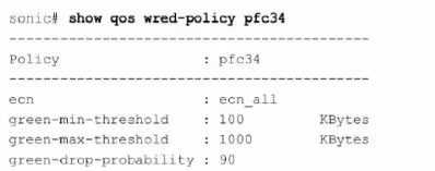
Refer to the exhibit.

What can be determined from this show command?
- Traffic below 100 KB is marked as congested
- ECN is enabled for all colors
- ECN is enabled for all DSCP values
- There is a 10% probability that traffic is marked as congested
Correct answer: B
Explanation:
The output of the command show qos wred-policy pfc34 shows the ECN (Explicit Congestion Notification) configuration for the policy pfc34. The line ecn: ecn_all indicates that ECN is enabled for all traffic classes (all DSCP values). Additionally, the green-min-threshold, green-max-threshold, and green-drop-probability settings are shown, but there is no indication of a 10% probability for marking traffic as congested. Therefore, the correct answer is B.Dell Enterprise SONiC documentationDell Technologies InfoHub The output of the command show qos wred-policy pfc34 shows the ECN (Explicit Congestion Notification) configuration for the policy pfc34. The line ecn: ecn_all indicates that ECN is enabled for all traffic classes (all DSCP values). Additionally, the green-min-threshold, green-max-threshold, and green-drop-probability settings are shown, but there is no indication of a 10% probability for marking traffic as congested. Therefore, the correct answer is B.
Dell Enterprise SONiC documentation
Dell Technologies InfoHub
Question 10
How many port channels can be assigned to a single port?
- 8
- 2
- 4
- 1
Correct answer: D
Explanation:
According to the Dell SONiC documentation, a single physical port can be a member of only one port channel at a time. This restriction ensures the consistency and integrity of link aggregation configurations.Dell Networking SONiC: How to Configure Port ChannelsDell Technologies InfoHub According to the Dell SONiC documentation, a single physical port can be a member of only one port channel at a time. This restriction ensures the consistency and integrity of link aggregation configurations.
Dell Networking SONiC: How to Configure Port Channels
Dell Technologies InfoHub
HOW TO OPEN VCE FILES
Use VCE Exam Simulator to open VCE files

HOW TO OPEN VCEX AND EXAM FILES
Use ProfExam Simulator to open VCEX and EXAM files


ProfExam at a 20% markdown
You have the opportunity to purchase ProfExam at a 20% reduced price
Get Now!


