Download Designing Cisco Enterprise Networks (300-420 ENSLD).300-420.Pass4Sure.2020-01-09.25q.vcex
| Vendor: | Cisco |
| Exam Code: | 300-420 |
| Exam Name: | Designing Cisco Enterprise Networks (300-420 ENSLD) |
| Date: | Jan 09, 2020 |
| File Size: | 3 MB |
How to open VCEX files?
Files with VCEX extension can be opened by ProfExam Simulator.
Discount: 20%
Demo Questions
Question 1
Instructions
The main screen consists of two parts; the Main scenario and the Topology tabs. The main scenario describes TSHOOT.com test bed. The Topology tabs allow you to display the appropriate and select the trouble ticket.
To complete the item, you will first need to familiarize yourself with the TSHOOT.com test bed by clicking on the master scenario first and then the topologies tabs. Once you are familiar with the test bed and the topologies, you should start evaluating the trouble ticket. You will be presented with a Trouble Ticket scenario that will describe the fault condition. You will need to determine on which device the fault condition is located, to which technology the fault condition is related, and the solution to each trouble ticket. This will be done by answering three questions.
Ticket Selection
To begin, click on the Ticket on the Topology tabs.
Please note. Some of the questions will require you to use the scroll bar to see all options.
Fault Isolation
Read the ticket scenario to understand the fault condition.
Open the appropriate topology, based upon the ticket scenario.
Open the console of the desired device by clicking on that device in the topology, based upon your troubleshooting methodology.
Use the supported show, ping and trace commands to begin your fault isolation process.
Move to other devices as need by clicking on those devices within the topology.
Fault Identification
The trouble ticket will include three questions that you will need to answer:
- Which device contains the fault
- Which technology the fault condition is related to
- What is the solution to the issue
To advance to the next question within the ticket click on “Next Question”.
When you click “DONE”, the trouble ticket will turn RED and will no longer be accessible.
You may also use the “Previous Question” button to review questions within that specific ticket.
To complete a trouble ticket, answer all three questions and click “DONE”. This will store your response to the questions. Do not click on “DONE” unless you have answered all questions within the ticket.
Item Completion
Click the NEXT button on the bottom of the screen once a ticket is RED. This action moves you to the next item.
Scenario
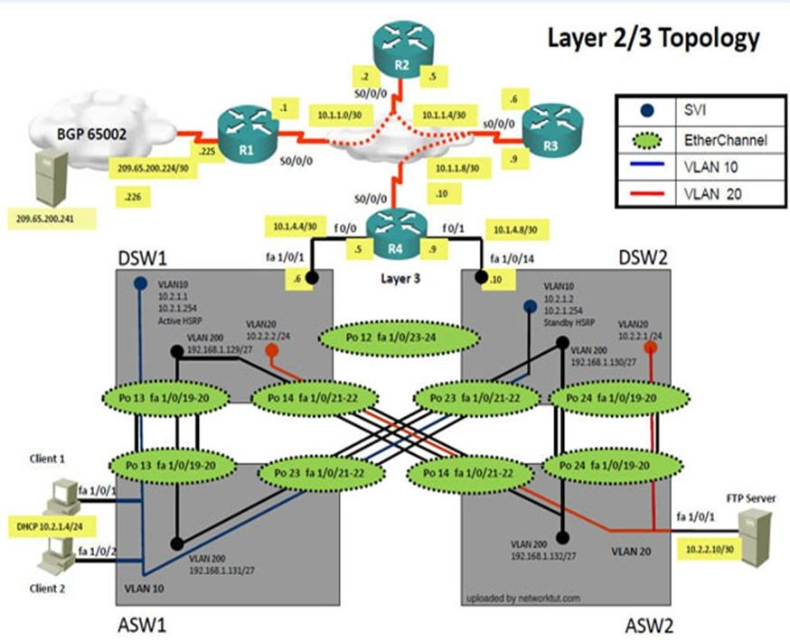
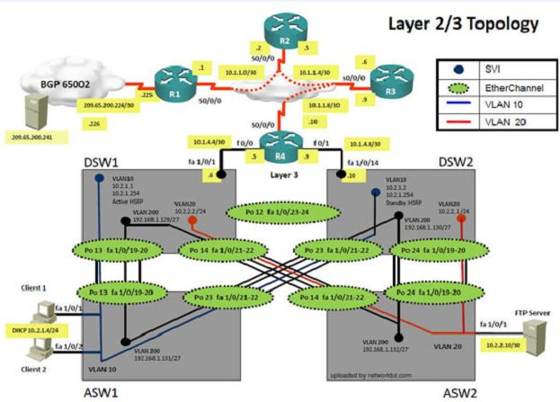
The company has created the test bed network shown in the layer 2 and layer 3 topology exhibits.
This network consists of four routers, two layer 3 switches and two layer 2 switches.
In the IPv4 layer 3 topology, R1, R2, R3, and R4 are running OSPF with an OSPF process number 1.
DSW1, DSW2 and R4 are running EIGRP with an AS of 10. Redistribution is enabled where necessary.
R1 is running a BGP AS with a number of 65001. This AS has an eBGP connection to AS 65002 in the ISP’s network. Because the company’s address space is in the private range, R1 is also providing NAT translations between the inside (10.1.0.0/16 & 10.2.0.0/16) networks and the outside (209.65.200.0/24) network.
ASW1 and ASW2 are layer 2 switches.
NTP is enabled on all devices with 209.65.200.226 serving as the master clock source.
The client workstations receive their IP address and default gateway via R4’s DHCP server. The default gateway address of 10.2.1.254 is the IP address of HSRP group 10 which is running on DSW1 and DSW2.
In the IPv6 layer 3 topology R1, R2, and R3 are running OSPFv3 with an OSPF process number 6. DSW1, DSW2 and R4 are running RIPng process name RIP_ZONE. The two IPv6 routing domains, OSPF 6 and RIPng are connected via GRE tunnel running over the underlying IPv4 OSPF domain. Redistribution is enabled where necessary.
Recently the implementation group has been using the test bed to do a ‘proof-of-concept’ on several implementations. This involved changing the configuration on one or more of the devices. You will be presented with a series of trouble tickets related to issues introduced during these configurations.

The implementation group has been using the test bed to do a ‘proof-of-concept’ that requires both Client 1 and Client 2 to access the WEB Server at 209.65.200.241. After several changes to the network addressing, routing schemes, DHCP services, NTP services, and FHRP services, a trouble ticket has been opened indicating that Client 1 cannot ping the 209.65.200.241 address.
Use the supported commands to isolate the cause of this fault and answer the following questions.
On which device is the fault condition located?
- R1
- R2
- R3
- R4
- DSW1
- DSW2
- ASW1
- ASW2
Correct answer: G
Explanation:
Steps need to follow as below:-1.When we check on client 1 & Client 2 desktop we are not receiving DHCP address from R4Ipconfig ----- Client will be getting 169.X.X.X2.On ASW1 port Fa1/0/ 1 & Fa1/0/2 access port VLAN 10 was assigned which is using IPaddress 10.2.1.0/24Sh run ------- & check for running config of int fa1/0/1 & fa1/0/2====================================================interface FastEthernet1/0/1switchport mode accessswitchport access vlan 10interface FastEthernet1/0/2switchport mode accessswitchport access vlan 10====================================================3.We need to check on ASW 1 trunk port the trunk Po13 & Po23 were receiving VLAN 20 &200 but not VLAN 10 so that switch could not get DHCP IP address and was failing to reach IPaddress of Internet4. Change required:On ASW1 below change is required for switch-to-switch connectivity..int range portchannel13,portchannel23switchport trunk allowed vlan noneswitchport trunk allowed vlan 10,200 Steps need to follow as below:-1.When we check on client 1 & Client 2 desktop we are not receiving DHCP address from R4Ipconfig ----- Client will be getting 169.X.X.X2.On ASW1 port Fa1/0/ 1 & Fa1/0/2 access port VLAN 10 was assigned which is using IPaddress 10.2.1.0/24Sh run ------- & check for running config of int fa1/0/1 & fa1/0/2====================================================interface FastEthernet1/0/1switchport mode accessswitchport access vlan 10interface FastEthernet1/0/2switchport mode accessswitchport access vlan 10====================================================
3.We need to check on ASW 1 trunk port the trunk Po13 & Po23 were receiving VLAN 20 &200 but not VLAN 10 so that switch could not get DHCP IP address and was failing to reach IPaddress of Internet4.
Change required:
On ASW1 below change is required for switch-to-switch connectivity..int range portchannel13,portchannel23switchport trunk allowed vlan noneswitchport trunk allowed vlan 10,200
Question 2
Instructions
The main screen consists of two parts; the Main scenario and the Topology tabs. The main scenario describes TSHOOT.com test bed. The Topology tabs allow you to display the appropriate and select the trouble ticket.
To complete the item, you will first need to familiarize yourself with the TSHOOT.com test bed by clicking on the master scenario first and then the topologies tabs. Once you are familiar with the test bed and the topologies, you should start evaluating the trouble ticket. You will be presented with a Trouble Ticket scenario that will describe the fault condition. You will need to determine on which device the fault condition is located, to which technology the fault condition is related, and the solution to each trouble ticket. This will be done by answering three questions.
Ticket Selection
To begin, click on the Ticket on the Topology tabs.
Please note. Some of the questions will require you to use the scroll bar to see all options.
Fault Isolation
Read the ticket scenario to understand the fault condition.
Open the appropriate topology, based upon the ticket scenario.
Open the console of the desired device by clicking on that device in the topology, based upon your troubleshooting methodology.
Use the supported show, ping and trace commands to begin your fault isolation process.
Move to other devices as need by clicking on those devices within the topology.
Fault Identification
The trouble ticket will include three questions that you will need to answer:
- Which device contains the fault
- Which technology the fault condition is related to
- What is the solution to the issue
To advance to the next question within the ticket click on “Next Question”.
When you click “DONE”, the trouble ticket will turn RED and will no longer be accessible.
You may also use the “Previous Question” button to review questions within that specific ticket.
To complete a trouble ticket, answer all three questions and click “DONE”. This will store your response to the questions. Do not click on “DONE” unless you have answered all questions within the ticket.
Item Completion
Click the NEXT button on the bottom of the screen once a ticket is RED. This action moves you to the next item.
Scenario
The company has created the test bed network shown in the layer 2 and layer 3 topology exhibits.
This network consists of four routers, two layer 3 switches and two layer 2 switches.
In the IPv4 layer 3 topology, R1, R2, R3, and R4 are running OSPF with an OSPF process number 1.
DSW1, DSW2 and R4 are running EIGRP with an AS of 10. Redistribution is enabled where necessary.
R1 is running a BGP AS with a number of 65001. This AS has an eBGP connection to AS 65002 in the ISP’s network. Because the company’s address space is in the private range, R1 is also providing NAT translations between the inside (10.1.0.0/16 & 10.2.0.0/16) networks and the outside (209.65.200.0/24) network.
ASW1 and ASW2 are layer 2 switches.
NTP is enabled on all devices with 209.65.200.226 serving as the master clock source.
The client workstations receive their IP address and default gateway via R4’s DHCP server. The default gateway address of 10.2.1.254 is the IP address of HSRP group 10 which is running on DSW1 and DSW2.
In the IPv6 layer 3 topology R1, R2, and R3 are running OSPFv3 with an OSPF process number 6. DSW1, DSW2 and R4 are running RIPng process name RIP_ZONE. The two IPv6 routing domains, OSPF 6 and RIPng are connected via GRE tunnel running over the underlying IPv4 OSPF domain. Redistribution is enabled where necessary.
Recently the implementation group has been using the test bed to do a ‘proof-of-concept’ on several implementations. This involved changing the configuration on one or more of the devices. You will be presented with a series of trouble tickets related to issues introduced during these configurations.
The implementation group has been using the test bed to do a ‘proof-of-concept’ that requires both Client 1 and Client 2 to access the WEB Server at 209.65.200.241. After several changes to the network addressing, routing schemes, DHCP services, NTP services, and FHRP services, a trouble ticket has been opened indicating that Client 1 cannot ping the 209.65.200.241 address.
Use the supported commands to isolate the cause of this fault and answer the following questions.
The fault condition is related to which technology?
- NTP
- Switch-to-Switch Connectivity
- Loop Prevention
- Access Vlans
- Port Security
- VLAN ACL / Port ACL
- Switch Virtual Interface
Correct answer: B
Explanation:
Steps need to follow as below:-1.When we check on client 1 & Client 2 desktop we are not receiving DHCP address from R4Ipconfig ----- Client will be getting 169.X.X.X2.On ASW1 port Fa1/0/ 1 & Fa1/0/2 access port VLAN 10 was assigned which is using IPaddress 10.2.1.0/24Sh run ------- & check for running config of int fa1/0/1 & fa1/0/2====================================================interface FastEthernet1/0/1switchport mode accessswitchport access vlan 10interface FastEthernet1/0/2switchport mode accessswitchport access vlan 10====================================================3.We need to check on ASW 1 trunk port the trunk Po13 & Po23 were receiving VLAN 20 &200 but not VLAN 10 so that switch could not get DHCP IP address and was failing to reach IPaddress of Internet4. Change required:On ASW1 below change is required for switch-to-switch connectivity..int range portchannel13,portchannel23switchport trunk allowed vlan noneswitchport trunk allowed vlan 10,200 Steps need to follow as below:-1.When we check on client 1 & Client 2 desktop we are not receiving DHCP address from R4Ipconfig ----- Client will be getting 169.X.X.X2.On ASW1 port Fa1/0/ 1 & Fa1/0/2 access port VLAN 10 was assigned which is using IPaddress 10.2.1.0/24Sh run ------- & check for running config of int fa1/0/1 & fa1/0/2====================================================interface FastEthernet1/0/1switchport mode accessswitchport access vlan 10interface FastEthernet1/0/2switchport mode accessswitchport access vlan 10====================================================
3.We need to check on ASW 1 trunk port the trunk Po13 & Po23 were receiving VLAN 20 &200 but not VLAN 10 so that switch could not get DHCP IP address and was failing to reach IPaddress of Internet4.
Change required:
On ASW1 below change is required for switch-to-switch connectivity..int range portchannel13,portchannel23switchport trunk allowed vlan noneswitchport trunk allowed vlan 10,200
Question 3
Instructions
The main screen consists of two parts; the Main scenario and the Topology tabs. The main scenario describes TSHOOT.com test bed. The Topology tabs allow you to display the appropriate and select the trouble ticket.
To complete the item, you will first need to familiarize yourself with the TSHOOT.com test bed by clicking on the master scenario first and then the topologies tabs. Once you are familiar with the test bed and the topologies, you should start evaluating the trouble ticket. You will be presented with a Trouble Ticket scenario that will describe the fault condition. You will need to determine on which device the fault condition is located, to which technology the fault condition is related, and the solution to each trouble ticket. This will be done by answering three questions.
Ticket Selection
To begin, click on the Ticket on the Topology tabs.
Please note. Some of the questions will require you to use the scroll bar to see all options.
Fault Isolation
Read the ticket scenario to understand the fault condition.
Open the appropriate topology, based upon the ticket scenario.
Open the console of the desired device by clicking on that device in the topology, based upon your troubleshooting methodology.
Use the supported show, ping and trace commands to begin your fault isolation process.
Move to other devices as need by clicking on those devices within the topology.
Fault Identification
The trouble ticket will include three questions that you will need to answer:
- Which device contains the fault
- Which technology the fault condition is related to
- What is the solution to the issue
To advance to the next question within the ticket click on “Next Question”.
When you click “DONE”, the trouble ticket will turn RED and will no longer be accessible.
You may also use the “Previous Question” button to review questions within that specific ticket.
To complete a trouble ticket, answer all three questions and click “DONE”. This will store your response to the questions. Do not click on “DONE” unless you have answered all questions within the ticket.
Item Completion
Click the NEXT button on the bottom of the screen once a ticket is RED. This action moves you to the next item.
Scenario
The company has created the test bed network shown in the layer 2 and layer 3 topology exhibits.
This network consists of four routers, two layer 3 switches and two layer 2 switches.
In the IPv4 layer 3 topology, R1, R2, R3, and R4 are running OSPF with an OSPF process number 1.
DSW1, DSW2 and R4 are running EIGRP with an AS of 10. Redistribution is enabled where necessary.
R1 is running a BGP AS with a number of 65001. This AS has an eBGP connection to AS 65002 in the ISP’s network. Because the company’s address space is in the private range, R1 is also providing NAT translations between the inside (10.1.0.0/16 & 10.2.0.0/16) networks and the outside (209.65.200.0/24) network.
ASW1 and ASW2 are layer 2 switches.
NTP is enabled on all devices with 209.65.200.226 serving as the master clock source.
The client workstations receive their IP address and default gateway via R4’s DHCP server. The default gateway address of 10.2.1.254 is the IP address of HSRP group 10 which is running on DSW1 and DSW2.
In the IPv6 layer 3 topology R1, R2, and R3 are running OSPFv3 with an OSPF process number 6. DSW1, DSW2 and R4 are running RIPng process name RIP_ZONE. The two IPv6 routing domains, OSPF 6 and RIPng are connected via GRE tunnel running over the underlying IPv4 OSPF domain. Redistribution is enabled where necessary.
Recently the implementation group has been using the test bed to do a ‘proof-of-concept’ on several implementations. This involved changing the configuration on one or more of the devices. You will be presented with a series of trouble tickets related to issues introduced during these configurations.
The implementation group has been using the test bed to do a ‘proof-of-concept’ that requires both Client 1 and Client 2 to access the WEB Server at 209.65.200.241. After several changes to the network addressing, routing scheme, DHCP services, NTP services, and FHRP services, a trouble ticket has been opened indicating that Client 1 cannot ping the 209.65.200.241 address.
Use the supported commands to isolate the cause of this fault and answer the following questions.
What is the solution to the fault condition?
- In configuration mode, using the interface range port-channel 23, port-channel 24, then configure switchport trunk allowed vlan none followed by switchport trunk allowed vlan 10,20,200 commands.
- In configuration mode, using the interface range port-channel 13, port-channel 23, then configure switchport trunk allowed vlan none followed by switchport trunk allowed vlan 10,200 commands.
- In configuration mode, using the interface range port-channel 23, port-channel 24, then configure switchport trunk allowed vlan none followed by switchport trunk allowed vlan 10,20, commands.
- In configuration mode, using the interface range port-channel 13, port-channel 23, then configure switchport trunk allowed vlan 10,200 followed by interface Fastethernet 1/0/1, then no shutdown commands.
Correct answer: B
Explanation:
Solution Steps need to follow as below:-1.When we check on client 1 & Client 2 desktop we are not receiving DHCP address from R4Ipconfig ----- Client will be getting 169.X.X.X2.On ASW1 port Fa1/0/ 1 & Fa1/0/2 access port VLAN 10 was assigned which is using IPaddress 10.2.1.0/24Sh run ------- & check for running config of int fa1/0/1 & fa1/0/2====================================================interface FastEthernet1/0/1switchport mode accessswitchport access vlan 10interface FastEthernet1/0/2switchport mode accessswitchport access vlan 10====================================================3.We need to check on ASW 1 trunk port the trunk Po13 & Po23 were receiving VLAN 20 &200 but not VLAN 10 so that switch could not get DHCP IP address and was failing to reach IPaddress of Internet4. Change required:On ASW1 below change is required for switch-to-switch connectivity..int range portchannel13,portchannel23switchport trunk allowed vlan noneswitchport trunk allowed vlan 10,200 Solution
Steps need to follow as below:-1.When we check on client 1 & Client 2 desktop we are not receiving DHCP address from R4Ipconfig ----- Client will be getting 169.X.X.X2.On ASW1 port Fa1/0/ 1 & Fa1/0/2 access port VLAN 10 was assigned which is using IPaddress 10.2.1.0/24Sh run ------- & check for running config of int fa1/0/1 & fa1/0/2====================================================interface FastEthernet1/0/1switchport mode accessswitchport access vlan 10interface FastEthernet1/0/2switchport mode accessswitchport access vlan 10====================================================
3.We need to check on ASW 1 trunk port the trunk Po13 & Po23 were receiving VLAN 20 &200 but not VLAN 10 so that switch could not get DHCP IP address and was failing to reach IPaddress of Internet4.
Change required:
On ASW1 below change is required for switch-to-switch connectivity..int range portchannel13,portchannel23switchport trunk allowed vlan noneswitchport trunk allowed vlan 10,200
Question 4
The implementations group has been using the test bed to do a ‘proof-of-concept’ that requires both Client 1 and Client 2 to access the WEB Server at 209.65.200.241. After several changes to the network addressing, routing scheme, DHCP services, NTP services, layer 2 connectivity, FHRP services, and device security, a trouble ticket has been opened indicating that Client 1 cannot ping the 209.65.200.241 address.
Use the supported commands to isolated the cause of this fault and answer the following questions.
The fault condition is related to which technology?
- BGP
- NTP
- IP NAT
- IPv4 OSPF Routing
- IPv4 OSPF Redistribution
- IPv6 OSPF Routing
- IPv4 layer 3 security
Correct answer: D
Explanation:
On R1, for IPV4 authentication of OSPF the command is missing and required to configure------ ip ospf authentication message-digest On R1, for IPV4 authentication of OSPF the command is missing and required to configure------ ip ospf authentication message-digest
Question 5
The implementations group has been using the test bed to do a ‘proof-of-concept’ that requires both Client 1 and Client 2 to access the WEB Server at 209.65.200.241. After several changes to the network addressing, routing scheme, DHCP services, NTP services, layer 2 connectivity, FHRP services, and device security, a trouble ticket has been opened indicating that Client 1 cannot ping the 209.65.200.241 address.
Use the supported commands to isolated the cause of this fault and answer the following questions.
What is the solution to the fault condition?
- Enable OSPF authentication on the s0/0/0 interface using the ip ospf authentication message-digest command
- Enable OSPF routing on the s0/0/0 interface using the network 10.1.1.0 0.0.0.255 area 12 command.
- Enable OSPF routing on the s0/0/0 interface using the network 209.65.200.0 0.0.0.255 area 12 command.
- Redistribute the BGP route into OSPF using the redistribute BGP 65001 subnet command.
Correct answer: A
Explanation:
On R1, for IPV4 authentication of OSPF the command is missing and required to configure------ ip ospf authentication message-digest On R1, for IPV4 authentication of OSPF the command is missing and required to configure------ ip ospf authentication message-digest
Question 6
The implementations group has been using the test bed to do a ‘proof-of-concept’ that requires both Client 1 and Client 2 to access the WEB Server at 209.65.200.241. After several changes to the network addressing, routing scheme, DHCP services, NTP services, layer 2 connectivity, FHRP services, and device security, a trouble ticket has been opened indicating that Client 1 cannot ping the 209.65.200.241 address.
Use the supported commands to isolated the cause of this fault and answer the following questions.
The fault condition is related to which technology?
- BGP
- NTP
- IP NAT
- IPv4 OSPF Routing
- IPv4 OSPF Redistribution
- IPv6 OSPF Routing
- IPv4 layer 3 security
Correct answer: C
Explanation:
On R1 we need to add the client IP address for reachability to server to the access list that is used to specify which hosts get NATed. On R1 we need to add the client IP address for reachability to server to the access list that is used to specify which hosts get NATed.
Question 7
Refer to the exhibit. PC-2 failed to establish a Telnet connection to the Terminal Server. Which solution allows PC-2 to establish the Telnet connection?
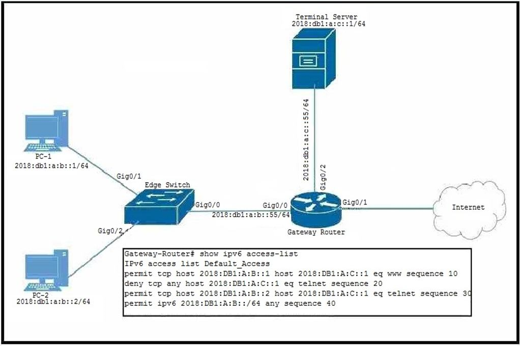
- Gateway-Router(config)#ipv6 access-list Default_AccessGateway-Router(config-ipv6-acl)#no sequence 20Gateway-Router(config-ipv6-acl)#sequence 5 permit tcp host 2018:DB1:A:B::2 host 2018:DB1:A:C::1 eq telnet
- Gateway-Router(config)#ipv6 access-list Default_AccessGateway-Router(config-ipv6-acl)#permit tcp host 2018:DB1:A:B::2 host 2018:DB1:A:C::1 eq telnet
- Gateway-Router(config)#ipv6 access-list Default_AccessGateway-Router(config-ipv6-acl)#sequence 15 permit tcp host 2018:DB1:A:B::2 host 2018:DB1:A:C::1 eq telnet
- Gateway-Router(config)#ipv6 access-list Default_AccessGateway-Router(config-ipv6-acl)#sequence 25 permit tcp host 2018:DB1:A:B::2 host 2018:DB1:A:C::1 eq telnet
Correct answer: B
Question 8
Refer to the exhibit. MTU has been configured as shown, and no MTU command has been configured on the tunnel interfaces. It has been found that fragmentation is occurring when tunneled packets are placed onto the IPv6 underlay network. Which configuration change will resolve this problem?
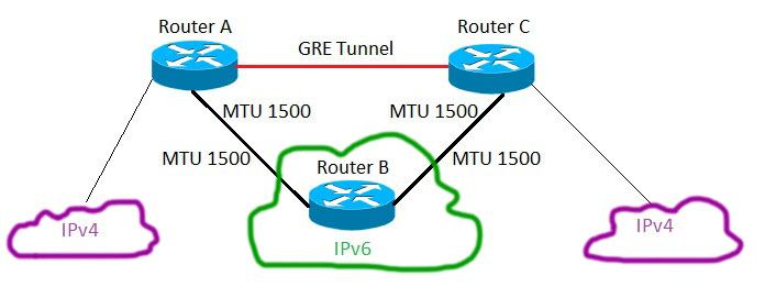
- Set the MTU to 1476 on the tunnel interfaces
- Increase the MTU on the IPv6 network
- Set the MTU to 1500 on the tunnel interfaces
- Increase the MTU on the IPv4 networks
Correct answer: A
Question 9
Refer to the exhibit.
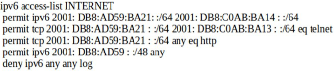
Which statement about the INTERNET ACL is true?
- The denied entries will be logged because of the explicit deny ipv6 any any log line.
- A packet with a source address of 2001:DB8:AD59:ACC0:2020:882:DB8:1125 will be denied.
- HTTPS traffic from the 2001:DB8:AD59:BA21::/64 subnet will automatically be permitted along with HTTP traffic.
- A packet with a source address of 2001:DB80:AD59:BA21:101:CAB:64:38 destined to port 80 will be permitted.
Correct answer: D
Question 10
Refer to the exhibit. An IPv6 network was just deployed in the environment and the help desk has reported that R3 is not able to SSH to R2’s Loopback interface. Which sequence number of the filter is preventing access?
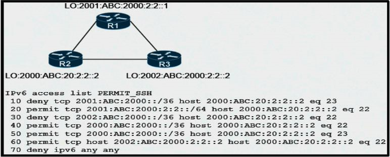
- 10
- 20
- 30
- 70
Correct answer: C
HOW TO OPEN VCE FILES
Use VCE Exam Simulator to open VCE files
HOW TO OPEN VCEX AND EXAM FILES
Use ProfExam Simulator to open VCEX and EXAM files
ProfExam at a 20% markdown
You have the opportunity to purchase ProfExam at a 20% reduced price
Get Now!